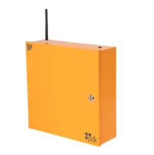
 2 Doors Access Control Metal Enclosure
Shop
Alarm.com Access Control Door Controller and Power Supply
$1,100.00
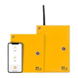
The Alarm.com Access Control Door Controller and Power Supply is everything you need to get started to add access control to your alarm.com security system. You can also control the doors in your business with the same app that you use to control your alarm system. You can also manage users and their permissions and schedules from the same alarm.com web portal. Just log in and start adding, removing, or editing access to your employees. It’s that easy! (Well, we have to install this control panel first, as well as then add a reader, etc…)
In order to use this, you must also subscribe to Alarm.com service with Zions Security Alarms.
Description
The Alarm.com Access Control Door Controller and Power Supply are everything you need to get started to add access control to your alarm.com security system. You can also control the doors in your business with the same app that you use to control your alarm system. You can also manage users and their permissions and schedules from the same alarm.com web portal. Just log in and start adding, removing, or editing access to your employees. It’s that easy! (Well, we have to install this control panel first, as well as then add a reader, etc…)
In order to use this, you must also subscribe to Alarm.com service with Zions Security Alarms.
Features of The Alarm.com Access Control Door Controller and Power Supply:
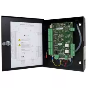
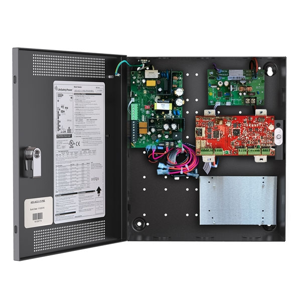
- Steel Enclosure with holes for air circulation and lock
- Door Controller that can support two readers
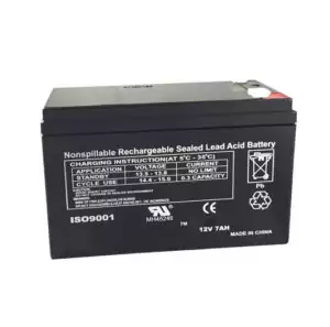
- The power Supply is ready to be plugged into power as well as ready to have a backup battery added
- Mounting plate for a single or two reader expansion module
- Extra parts (screws) for expansion modules
The Alarm.com Access Control Door Controller and Power Supply provide local decision-making, event reporting, and database storage capabilities for the Alarm.com Smarter Access Control platform. Two reader interfaces provide control for one supervised physical barrier or two unsupervised physical barriers.
Reader port 1 can accommodate a Wiegand reader and provides LED and buzzer control. This port can alternatively utilize a two-wire RS-485 bus to connect up to eight Alarm.com expansion modules. Reader port 2 can accommodate a Wiegand reader and provides LED and buzzer control.
General:
To control locking hardware use Two Form-C contact relay outputs. The relay contacts are rated at 2A @ 30V DC, dry contact configuration. Additionally, the two inputs that are provided may be used for monitoring door position switches or request-to-exit devices. Input circuits can also be configured as unsupervised or supervised. The panel requires Power over Ethernet (PoE) or 12V DC for power. (This kit comes with the power supply already in place so you don’t have to worry about that)
Furthermore, the SRAM is backed up by a rechargeable battery when input power is removed. This battery should retain the data for a minimum of 3 days. It is also considered invalid and is erased if data in the SRAM is determined to be corrupt after power-up, all data, including flash memory. All configuration and cardholder data must be re-downloaded.
The initial charge of the battery may take up to 48 hours to be fully charged.
Additional Information:
The wiegand reader or up to eight Alarm.com expansion modules can use Reader port 1 to wire either one. In addition, to wire one Wiegand reader, Reader port 2 can be used. Power is supplied to reader port 1 at 12V DC at 180 mA maximum. Furthermore, you can power the reader connected to reader port 2 from the 12V DC auxiliary power output; TB4-1 and TB4-2. You should power separate readers that require different voltages or have high current requirements. Refer to the reader manufacturer specifications also for cabling requirements.
Reader port 1 can support up to eight Alarm.com expansion modules using a 2-wire RS-485 bus. The maximum cable length is also 2,000 ft. (610 m).
For additional readers with two LED wires, only connect the wire controlling the green LED to the panel.
When powering expansion modules as well as peripherals from the ADC-ACC1-17, be cautious not to exceed 650 mA @ 12V DC. 22 AWG minimum is recommended for readers.
Relay wiring:
Two Form-C contact relays are provided for controlling door lock mechanisms. The relay contacts are rated at 2A @ 30V DC, dry contact configuration. Each relay has a Common pole (C), a Normally Open pole (NO), and a Normally Closed pole (NC).
When momentarily delivering power to unlock the locking hardware (fail secure), it uses Normally Open and Common poles. When momentarily removing power to unlock the locking hardware (fail-safe), it also uses the Normally Closed and Common poles. Check with local building codes for proper egress door installation.
Further wiring:
Door lock mechanisms can generate EMF feedback to the relay circuit that can cause damage and premature failure of the relay. You should use either a diode or MOV (metal oxide varistor) to protect the relay for this reason.
Furthermore, from the Auxiliary output, the Alarm.com Access Control Door Controller and Power Supply can provide 12V DC power for external devices, provided they don’t exceed 650 mA. It must have a UL Listed Class 2 rating if a you use local power supply. 18 AWG minimum is recommended for electric locking hardware.
Input wiring
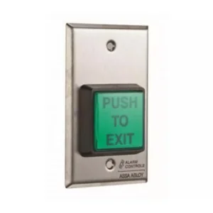
Inputs are used to monitor door position switches or request-to-exit devices. You can configure input circuits as unsupervised or supervised. When unsupervised, reporting consists of only the open or closed states.
Finally, when configured as supervised, the input circuit will report not only open and closed but also open circuit, shorted, grounded*, as well as foreign voltage*. A supervised input circuit requires you to add two resistors to the circuit to facilitate proper reporting. Additionally, The standard supervised circuit requires 1k ohm, 1% resistors, and should be located as close to the sensor as possible.
*Grounded as well as foreign voltage states are not a requirement of UL 294 and therefore not verified by UL.
22 AWG minimum is required for input wiring. 18 AWG recommended if wiring request-to-exit devices in series with locking hardware.
Specifications:
- The interface is for use in low voltage, also Class 2 circuits only.
- The installation of this device must also comply with all local fire and electrical codes.
- Result of INPUT POWER – PoE, PoE+, or 12 VDC, 1.8 A max
- Result of OUTPUT POWER – 12 VDC @625 mA, PoE+
- Dimensions: Without Bracket: 5.5 x 2.75 x 0.96″ With Bracket: 5.5 x 3.63 x 1.33”
- Temperature: – 32°F – 158°F operational -67°F – 185°F storage
- Operating Humidity: – 5-95% (non-condensing) RH
Inputs:
- One dedicated reader input
- One switchable reader/two-wire RS-485 input Two programmable inputs
- Additionally One dedicated tamper input
Outputs:
- Two relay outputs (2A @ 30V DC)
- Single-wire LED control
- Single-wire buzzer output
Certifications:
- HSPD-12/FIPS201 compliant UL 294 and UL 294B recognized ROHS
- FCC Part 15 Class A
- NIST certified encryption
Please check out our YouTube Channel for more information.

Felix Shellburg –
This enclosure looks good and it runs a smooth connection to my card reader. Also easy to manage with my app.