Shop
Extra Wide Gap Gate Set 24″ Armored Cable
$ 133.00
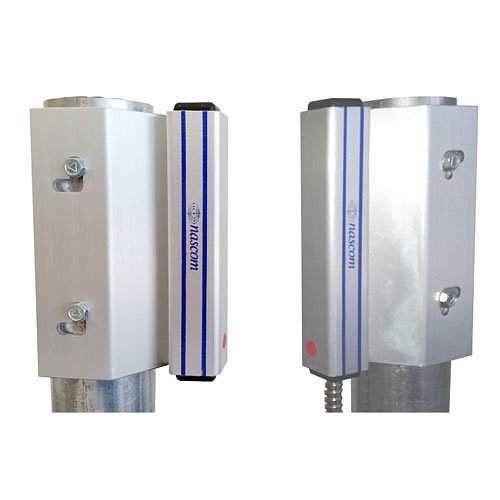
Extra Wide Gap Gate Set, 24″ Armored Cable Is An Extra Wide Gap Contact And Switch Set Designed For Gate Protection. It Combines The Installers’ Choice Of Contact Configuration With An N35 Ndfeb Magnet For Maximum Gap Performance. The N205xg Protects Single And Double Swing Gates.
Description
Product Overview
The Extra Wide Gap Gate Set, 24″ Armored Cable Prevents False Alarms Caused By Shifting Gates In High Wind Corridors And Features Our Unique No Dead Spot Technology.
Features
- No Dead Spot Technology
- 24″ Armored Cable Lead Protection
- Double N35 Ndfeb Rare Earth Magnets
- 36″ 22awg Wire Leads
- Listed To Ul634 Standard
- Extruded Anodized (type Ii) Aluminum
Main Features
- NO DEAD SPOT technology
- 24″ armored cable lead protection
- Double N35 Ndfeb rare earth magnets
Technical Features
- Contact Configuration N.O.
- Contact Resistance 150000 Micro Ohm
- Contact Resistance (Ohm) 0.15
- Lead Gauge 0.87″
- Lead Gauge (mm) 22
- Lead Length 36″
- Lead Length (mm) 914.4
- Magnet Type Permanent Magnet
- Mounting Type Surface Mount
- Recommended Use Gate
- Standard Gap 6″
- Standard Gap (mm) 152.4
- Termination Style Wire Leads
INSTALLATION INSTRUCTIONS
The N205XG is polarity sensitive and must be installed in the correct orientation to obtain optimal performance of the product.
• Unpack the switch and dual magnet set and separate the magnets. Note the RED dots on the ends of the switch and magnets.
• With the gate closed, pre-fit the switch on the gate post and magnets on the opposing gate post to ensure correct alignment and orientation can be achieved.
• Install the magnets on either side of the gate post with the ends of the magnets oriented with the red dots on the same end and the magnet housings aligned in parallel, see illustration below:
• Mark and drill the magnet mounting holes using a drill adequately sized for the type of fasteners to be used to secure the switch and magnet. Attach magnets to the gate post.
• Locate the switch on the opposing gate post so the red dot is aligned and oriented on the same end as the red dots on
the magnets.
• Make sure the ends of the switch and magnet housings are aligned, mark and drill the switch mounting holes using a
drill adequately sized for the type of fasteners to be used to secure the switch and magnets. Attach the switch to the opposing gate post.
• Connect the switch leads to an ohm meter and open and close the gate to test the switch for correct operation.
• Connect the switch leads to the alarm system.

Maria Mac –
Great product works well